前回に引き続き、mbed NXP LCP1768 でLEDにBitパターンを表示させる制御について。
今回は、PCからシリアル通信を通して、Bitパターンをカウントアップかカウントダウンか任意のタイミングで変更できるように変更する。
1.mbedとPCをシリアル通信が出来るように設定する。
兎にも角にも、まずはデバイス的にmbedとPCが繋がらなければならない。
Mac/Linux系だとUSBで接続するだけで通信が出来るようになるが、Windowsは設定が必要だ。
詳しくはこちらの記事などを参考に設定して欲しい。
2.Serial通信用クラスを追加する。
mbedではSerialというクラスが用意されている。此れを使って、Serial通信を行うことになる。
以下が実際のコードだ。
CtrlBase.hpp
#include"mbed.h"; Serial pc(USBTX, USBRX); Serial uart(p28, p27); class CtrlBase{ public: CtrlBase(Serial& tgt) : _refTarget(tgt){}; bool isReadable(){ return _refTarget.readable(); }; char getc(){ return _refTarget.getc(); }; void putc(char c){ _refTarget.putc(c); }; private: Serial& _refTarget; }; class CtrlPCSerial : public CtrlBase { public: CtrlPCSerial(): CtrlBase(pc){}; }; class CtrlUART : public CtrlBase{ public: CtrlUART(): CtrlBase(uart){}; };CtrlBaseが通信用のカプセルクラスだ。これを継承し、Serial用とUART用を用意している。
Serialクラスのサブクラスとしてやる方が実は良い。
しかし今回はC++ビギナーの方向けに、自作クラスを継承してサブクラスを作成する例として用意した。
”継承?”となる方は、色々ぐぐって検索してみよう。3.メイン処理を修正する。
ここまでできたのなら、後は簡単だ。
main.cppからCtrlBase.hppをインクルードし、カウントダウン/アップのロジックを実装するだけだ。#include "mbed.h" #include "CtrlBase.hpp" DigitalOut leds[] = {LED1, LED2, LED3, LED4}; int numLeds = sizeof(leds)/sizeof(DigitalOut); class CtrlLEDs{ public: static void ALLOFF(){ for(int i = 0 ; i < numLeds ; i++){ leds[i] = 0; } }; static void ON(int idx){ leds[idx] = 1; }; static void OFF(int idx){ leds[idx] = 0; }; static void ON_Bit(int flag) { if(numLeds < 4) return; leds[0] = ((flag & 0b1000) > 0) ? 1 : 0; leds[1] = ((flag & 0b0100) > 0) ? 1 : 0; leds[2] = ((flag & 0b0010) > 0) ? 1 : 0; leds[3] = ((flag & 0x0001) > 0) ? 1 : 0; printf("0x%04x Lighting.\r\n", flag); }; }; class Counter{ enum { DOWN = -1, UP = 1 }; public: Counter(int thresh, bool flg = true): _countSide(flg),_countValue(0), _threshValue(thresh) {}; void SetCountSide(bool flg){ _countSide = flg; printf("Counter: Mode Changed\r\n"); }; bool step(){ _countValue += _countSide ? UP : DOWN; if( _countSide ){ return _countValue < _threshValue; }else{ return _countValue >= 0; } }; void resetValue(){ _countValue = _countSide ? 0 : _threshValue; }; int getValue(){ return _countValue; }; private: bool _countSide; int _countValue; int _threshValue; }; int main() { CtrlPCSerial pc; CtrlUART uart; Counter myCounter(15); CtrlLEDs::ALLOFF(); char c; printf("Press \"0\" to set countdown. \"1\" to set countup.\r\n"); while(1) { if(pc.isReadable()){ c = pc.getc(); if(c == '0') myCounter.SetCountSide(false); if(c == '1') myCounter.SetCountSide(true); }; CtrlLEDs::ON_Bit(myCounter.getValue()); if(!myCounter.step()){ myCounter.resetValue(); } wait(0.5); } }Counterクラスでカウントダウン、カウントアップどちらであっても、操作性が同じになるようにカプセル化している。
後はメインループの中で、
1.PCとのシリアル通信で読み取り可能状態(文字入力されているか)をチェックする。
2.入力されていたら文字を読み込み、0 or 1を判定してBitパターンの点灯順を切り替える。
3.上限/下限に来たらリセットして1.から再スタート
とするだけだ。既にお分かりの通り、ある程度の処理単位でクラス化して操作を抽象化すると、
コードを読むだけで機能の類推がより容易になる。
只、やりすぎると却ってわかりづらくなってしまうので、気を付けよう。4.動作確認。
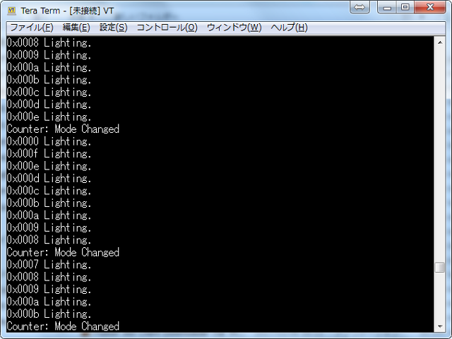
今回はLEDの点灯動画を用意し忘れていたが、代わりにログ画面を参考として貼っておく。
”Counter: Mode Changed”と表示されているところが、PCで0や1を入力したタイミングだ。
LEDの点灯も昇順/降順で切り替わっていることが確認できる。今回のソースコードはここにある。